Q: What about regular turn signals?
According to Roger: That is kind of a loaded question! Manufacturers vary
so much with wire colors and it is very difficult to just
say one fits them all. It seems a wire color standard is
not observed in the golf car industry. So it is imperative
that you have the correct diagram for the system
you are working on. With this said I have tried to keep our product as
close to a repetitive color scheme as possible. Most
turn signal heads are either a 4 or 8 wire design. The
4 wire design is used strictly for turn signals. The 8
wire is most widely used and will accommodate a
brake light circuit. We will only talk about the 8 wire
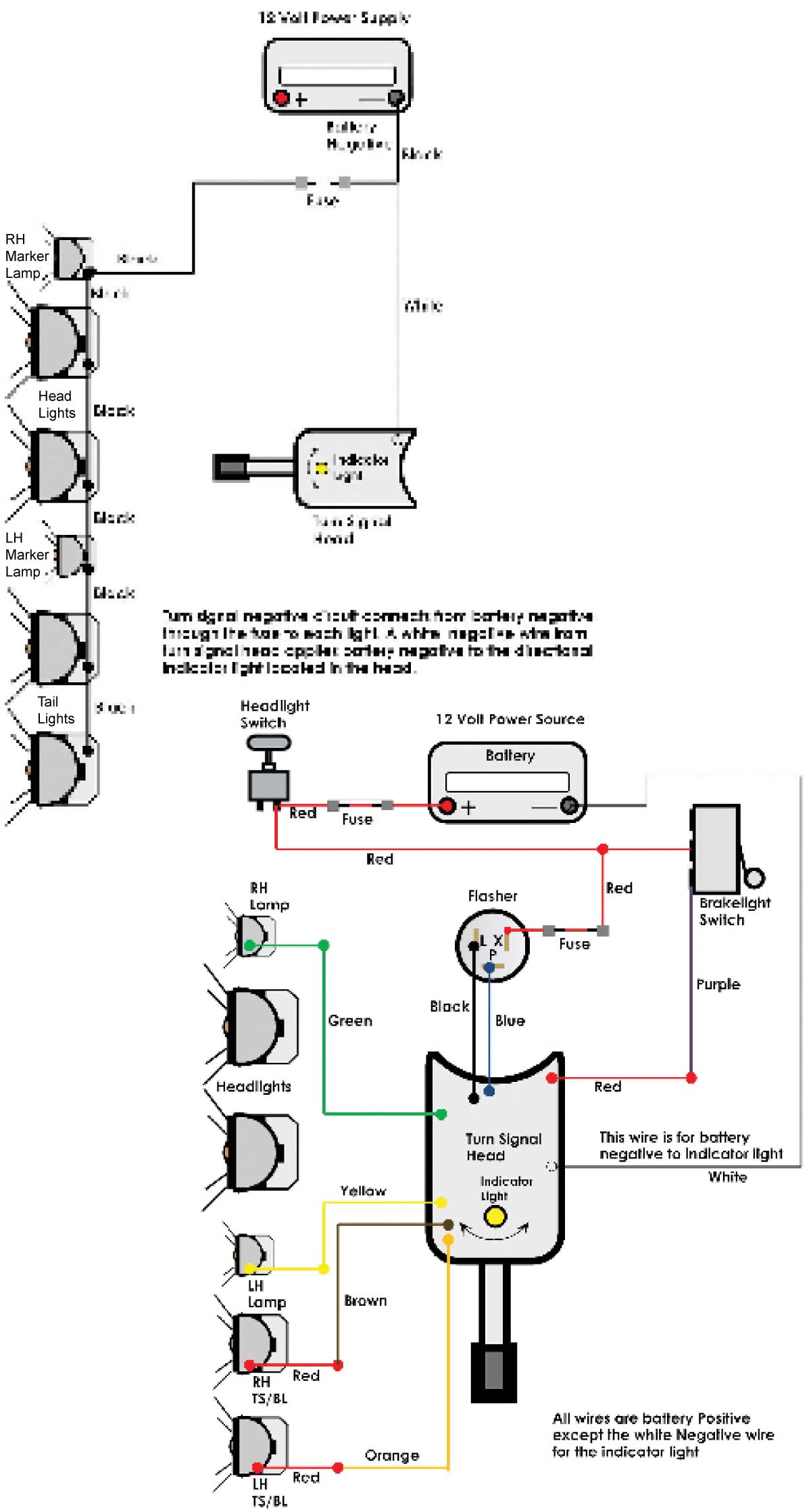
system. The head consists of 6 positive circuits. They are LH
turn front, RH turn front, LH turn rear, RH turn rear,
indicator light, and brake lights. Click here for Turn Signal Kit Wiring Diagram The next step is to bring in battery positive to the
flasher and to the turn signal head for proper distribution
to each circuit. Notice the flasher has three
connections. L is black wire load to the head. P is
blue wire power to the head. X is battery positive from
a 12-volt source. X is a red fused wire. Usually the
red X wire is connected to the headlight on/off switch.
Simply put, all this means is when moving the head
lever left or right you are only diverting battery positive
to each circuit! Now here is where most people get confused. Battery
negative pre-exists from the headlight circuit. The only
negative circuit to the turn signal head is the white
wire for the indicator light. You must also separate the front marker lamps from
the headlight circuit! Once separated the appropriate
wire can be connected. The rear lights must be a 3 wire design utilizing a
double filament bulb. |
Continue Shopping
MY CART (0)
Cart Subtotal:
$0.00